Exploring the Role of Potentiometers in Proportional Valve Driver Performance
Understanding Proportional Valve Drivers
What is a Proportional Valve Driver?
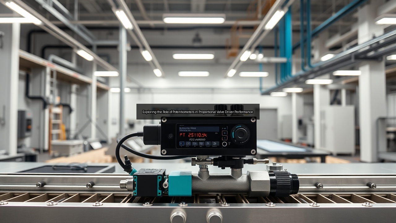
A proportional valve driver delivers precise control over hydraulic flow and pressure by modulating current to the solenoid coil in real time. Operators adjust command signals through an interface that scales output based on input voltage or current. This setup replaces simple on-off solenoid action with smooth, variable positioning that improves system response in mobile equipment and industrial machinery. The driver accepts inputs from joysticks or electronic control units and converts them into stable coil current, often using pulse-width modulation to maintain accuracy across temperature swings. In practice, technicians integrate the driver into existing hydraulic circuits to achieve repeatable valve spool movement without mechanical linkages. When paired with sensors, the unit maintains set points even under varying loads, reducing energy waste and heat generation in the power pack.
Key Components of Proportional Valve Drivers
Core elements include the power stage with H-bridge circuitry, signal conditioning amplifiers, and feedback pathways that monitor actual coil current. A microcontroller or dedicated IC processes command signals while protecting against short circuits and over-temperature conditions. DIN rail mounting options simplify installation in control cabinets, whereas compact PCB versions fit directly inside valve housings for mobile applications. Digital displays and 4 LED indicators provide at-a-glance status for power, fault, and output levels. Many units also incorporate SAE J1939 communication so engine control modules can command and monitor valve behavior over a CAN bus. These building blocks work together to translate low-level electronic instructions into high-current solenoid drive without sacrificing resolution or response speed.
Significance of Potentiometers in Valve Performance
The potentiometer serves as the primary manual or automated adjustment point for setting maximum current, ramp times, and dead-band compensation inside the proportional valve driver. Technicians turn a multi-turn potentiometer on the driver board to fine-tune voltage output to the coil, ensuring the valve reaches full stroke at the desired command level. This calibration step directly affects flow gain and system stability, especially when hydraulic oil temperature changes viscosity. In field service, a simple screwdriver adjustment on the potentiometer restores performance after coil replacement or pressure changes. Without accurate potentiometer settings, even the best amplifiers cannot deliver consistent spool positioning, leading to jerky cylinder motion or pressure overshoot. Proper use therefore translates into safer operation and longer component life across demanding hydraulic circuits.
The Functionality of Potentiometers in Hydraulic Systems

How Potentiometers Control Voltage Output
Inside the driver, a potentiometer divides reference voltage to produce an adjustable command that the power stage amplifies for the solenoid coil. Rotating the shaft changes resistance and therefore the voltage presented to the error amplifier, which then increases or decreases coil current proportionally. This direct relationship lets operators match valve flow curves to specific machine requirements without rewriting firmware. In cart-mounted test stands, engineers dial the potentiometer while monitoring pressure transducers to map the entire operating envelope. Because the adjustment is analog and continuous, it provides finer granularity than discrete digital steps in many legacy systems. Maintenance staff rely on this straightforward method when commissioning new valves or compensating for manufacturing tolerances in spool geometry.
The Role of Potentiometers in Feedback Loops
Feedback loops compare commanded current against actual coil current measured by a shunt resistor. The potentiometer sets the reference point that closes this loop and eliminates steady-state error. When load pressure rises and coil resistance increases, the loop automatically raises drive voltage to maintain the target current established by the potentiometer. This closed-loop behavior prevents the valve from drifting off the intended flow rate during extended duty cycles. In systems using both analog and digital potentiometers, the latter stores preset values that the microcontroller recalls on power-up, while the analog trimmer allows on-the-spot corrections. The combination yields both repeatability and flexibility in mobile hydraulic platforms operating across wide ambient temperature ranges.
Comparing Analog and Digital Potentiometers
Analog potentiometers offer immediate tactile adjustment and require no programming tools, making them popular for quick field calibration of proportional control valve drivers. Digital versions, however, store multiple curves and communicate settings over USB or near field communication (NFC) links, allowing remote updates without opening the enclosure. Technicians compare the two by measuring hysteresis and long-term drift; analog units can suffer from mechanical wear, whereas digital potentiometers maintain accuracy over millions of cycles. In North America, many fleets standardize on digital units for SAE J1939 networks because they integrate cleanly with existing electronic control architectures. Selection ultimately depends on whether the application prioritizes simplicity or advanced diagnostics and data logging.
Integration of Potentiometers with Proportional Valve Electronics
Interface Connections: DIN Rail and PCB Configurations
DIN rail drivers mount quickly in control panels and accept wiring from multiple valves through standardized terminal blocks. PCB-mounted versions reduce harness length by placing the potentiometer and amplifiers directly beside the solenoid connector. Both formats support the same core functions, yet the PCB approach saves space in compact machinery where every cubic inch matters. Installers verify pinouts against the drawing supplied with each unit to ensure correct polarity to the coil. Proper grounding and shielding prevent noise from corrupting the low-level potentiometer signal, preserving the resolution needed for smooth valve operation in electro-hydraulic systems.
The Impact of USB and NFC on Valve Communication
USB ports on modern proportional valve electronics enable laptop-based configuration of ramp rates, current limits, and fault thresholds stored in the driver’s memory. Near field communication (NFC) and near field communications tags allow wireless parameter changes simply by tapping a smartphone against the housing. This capability reduces downtime during commissioning because technicians no longer need to remove covers or connect cables in dusty environments. When combined with a digital potentiometer, the interface lets users upload preset profiles for different attachments without mechanical adjustment. The result is faster setup and consistent performance across fleets operating in construction, agriculture, and material handling.
Utilizing H-Bridge Circuits for Enhanced Performance
An H-bridge inside the driver reverses current polarity to the solenoid coil, enabling bidirectional spool control or dither that reduces static friction. The potentiometer establishes the forward and reverse current ceilings while the bridge switches at high frequency to produce smooth motion. Engineers tune dither amplitude and frequency through the same potentiometer network or via USB commands. This architecture improves valve response at low command levels and prevents spool sticking after long idle periods. In Pulsar technology valves, the H-bridge works in concert with integrated position feedback to achieve closed-loop accuracy previously available only in servo systems.
Case Studies and Applications
Real-World Applications of Proportional Control Valve Drivers
Proportional control valve driver units appear in refuse trucks, aerial lifts, and agricultural sprayers where smooth cylinder motion improves operator comfort and productivity. Maintenance crews adjust the potentiometer to match each implement’s flow requirements, eliminating the need for multiple fixed-displacement pumps. In one municipal fleet, retrofitting drivers reduced hydraulic oil temperature by 15 degrees and extended pump life by 30 percent. The same hardware supports both open-center and load-sensing circuits, giving designers flexibility when upgrading older machines. Field data confirm that accurate potentiometer calibration correlates directly with lower fuel consumption and fewer warranty claims.
Analyzing Axiomatic and Atos Valve Systems
Axiomatic drivers emphasize rugged packaging and wide supply voltage tolerance for harsh environments, while Atos electronics focus on high-resolution current control and integrated digital displays. Both brands rely on potentiometers for initial setup yet differ in communication options; Axiomatic units often include SAE J1939, whereas Atos models lean toward CANopen. Comparative testing shows similar steady-state accuracy once the potentiometer is dialed in, but Atos firmware provides more granular ramp profiles through USB. Fleet managers therefore choose based on existing CAN bus architecture and preferred service tools rather than raw performance metrics.
The Role of Pulsar Technology in Proportional Valves
Pulsar technology integrates high-speed solenoids with embedded position sensors and advanced driver electronics. The potentiometer still sets maximum current, but closed-loop algorithms continuously correct for temperature and supply voltage variations. This hybrid approach delivers servo-like precision at proportional prices. OEMs adopt Pulsar valves in high-cycle stamping presses and injection molding machines where repeatability directly affects part quality. Technicians appreciate that the same potentiometer adjustment procedure works across legacy and new Pulsar platforms, reducing training time when fleets standardize on one driver family.
Frequently Asked Questions about Proportional Valve Drivers
Common Issues with Potentiometers in Valve Systems
Dirt ingress, mechanical wear, and misadjustment rank as the most frequent potentiometer problems. Contamination changes resistance and causes erratic coil current, while worn wipers introduce dead zones that the feedback loop cannot fully compensate. Operators sometimes set the potentiometer too high, saturating the solenoid and overheating the coil. Regular inspection and sealing of adjustment access points prevent these issues. When problems arise, swapping the potentiometer or switching to a digital equivalent restores performance quickly without replacing the entire driver assembly.
Understanding Voltage and Coil Specifications
Most proportional valve drivers operate from 9 to 32 VDC and deliver up to 3 A continuous to the coil. Coil resistance typically ranges from 2 to 8 ohms depending on valve size, so the driver must supply the correct voltage to reach target current. The potentiometer directly scales maximum output, allowing one driver model to serve multiple valve families. Exceeding coil current ratings shortens solenoid life, while under-driving limits valve flow. Always cross-reference the valve drawing with driver specifications before final potentiometer adjustment.
Exploring the Future of Proportional Valve Technology in North America
North American manufacturers continue to embed more diagnostics and wireless interfaces into proportional valve electronics. Digital potentiometers paired with NFC will soon let technicians upload calibration data directly from cloud-based asset management systems. Integration with SAE J1939 and emerging Ethernet protocols will further blur the line between valve drivers and full vehicle controllers. As electric and hybrid machinery grows, demand for low-power, high-efficiency drivers increases, pushing development of smarter H-bridge designs and advanced feedback schemes. The fundamental role of the potentiometer remains, now augmented by software-defined precision and remote monitoring capabilities.
See Also
- SAE J1939 Protocol and Its Impact on Proportional Valve Drivers in North America
- The Future of Fluid Control Exploring Proportional Valve Electronics
- Integrating USB Technology with Proportional Valve Drivers for Enhanced Functionality
- The Benefits of Digital Displays in Proportional Valve Driver Systems
- A Comprehensive Guide to Understanding Proportional Control Valve Drivers